PRESSURE & TEMPERATURE RATINGS
| Working Pressure | 16bar |
| Shell Testing Pressure (x1.5) | 24bar |
| Seat Testing Pressure (x1.1) | 17.6bar |
| Working Temperature | -20°C … 110°C (EPDM) -10°C … 80°C (NBR) |
| Suitable Media | Water, Oil, Gas |
| Working Pressure | 16bar |
| Shell Testing Pressure (x1.5) | 24bar |
| Seat Testing Pressure (x1.1) | 17.6bar |
| Working Temperature | -20°C … 110°C (EPDM) -10°C … 80°C (NBR) |
| Suitable Media | Water, Oil, Gas |
| Part | Material |
| Body | Ductile Iron |
| Disc | Ductile Iron Aluminium Bronze Stainless Steel 304 Stainless Steel 316 |
| Stem | Stainless Steel 410 Stainless Steel 431 |
| Seat Ring | EPDM / NBR |
| O-Ring | EPDM / NBR |
| Bushing | Bronze |
| DN | (mm) (inch) |
150 6 |
200 8 |
225 9 |
250 10 |
300 12 |
350 14 |
375 15 |
400 16 |
450 18 |
500 20 |
550 22 |
| A | 133 | 175 | 190 | 201 | 242 | 267 | 320 | 316 | 344 | 380 | 432 | |
| B | 226 | 260 | 275 | 292 | 337 | 368 | 375 | 400 | 422 | 480 | 533 | |
| C | 30 | 34 | 34 | 34 | 34 | 40 | 52 | 52 | 52 | 64 | 70 | |
| L | 55 | 60 | 67 | 67 | 76 | 76 | 102 | 102 | 114 | 127 | 151 |
| DN | (mm) (inch) |
600 24 |
650 26 |
700 28 |
750 30 |
800 32 |
900 36 |
1000 40 |
1050 42 |
1100 44 |
1200 48 |
| A | 468 | 484 | 530 | 564 | 602 | 661 | 724 | 784 | 804 | 869 | |
| B | 562 | 540 | 626 | 660 | 666 | 722 | 806 | 865 | 820 | 938 | |
| C | 70 | 70 | 95 | 95 | 95 | 130 | 130 | 150 | 150 | 150 | |
| L | 151 | 172 | 165 | 167 | 188 | 203 | 216 | 251 | 252.5 | 276 |
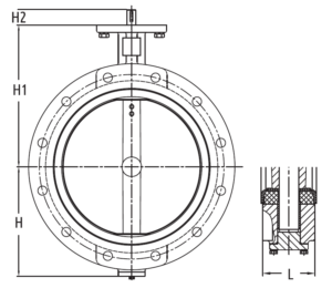
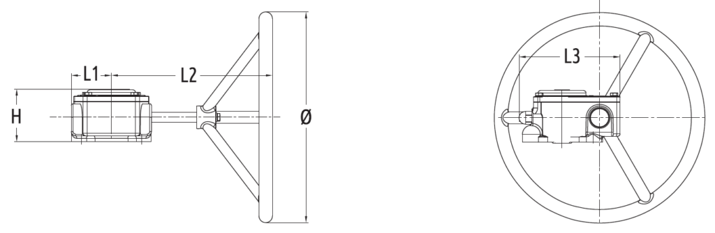
| Valve Diameter | D1 | ø | H | H1 | L1 | L2 | L3 |
| DN150 | 90 | 150 | 33 | 70 | 216 | 45 | 127 |
| DN200…DN250 | 125 | 285 | 36 | 76 | 303 | 63.5 | 170 |
| DN300…DN350 | 125 | 285 | 40 | 79 | 300 | 80 | 190 |
| DN375…DN400 | 175 | 385 | 79 | 323.5 | 300 | 80 | 190 |
| DN450…DN550 | 175 | 390 | 108 | 251 | 397/427 | 120 | 279 |
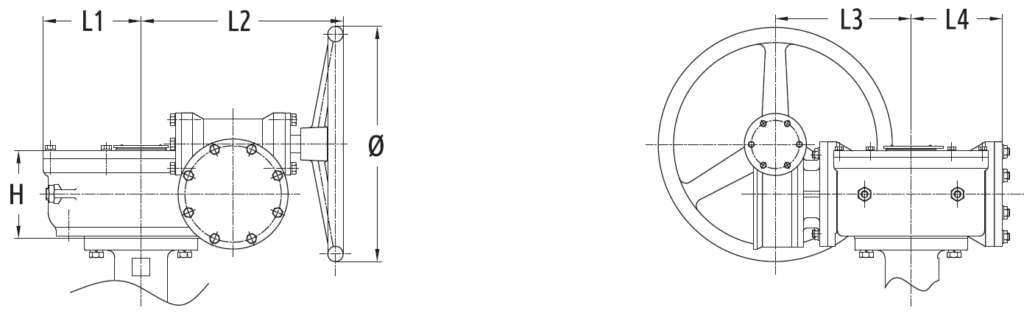
| Valve Diameter | D1 | ø | H | H1 | L1 | L2 | L3 | L4 | L5 |
| DN600…DN650 | 210 | 285 | 125 | 271 | 107 | 100 | 156 | 168 | 107 |
| DN700…DN800 | 300 | 425 | 149 | 378 | 146 | 140 | 197 | 230 | 146 |
| DN900…DN1050 | 300 | 425 | 185 | 409 | 201 | 196 | 203 | 279 | 201 |
| DN1100 | 350 | 425 | 185 | 409 | 201 | 196 | 203 | 279 | 201 |
| DN1200 | 350 | 425 | 216 | 423 | 185 | 240 | 203 | 311 | 255 |
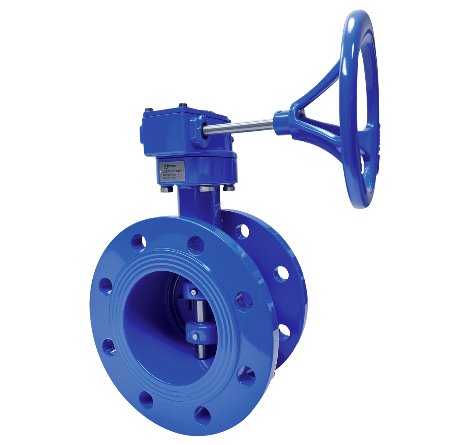
1. Ensure sufficient space for valves for easy installation, operation, maintenance and replacement.
2. Verify the valves are suitable for the operating condition such as medium, operating pressure / temperature, etc.
3. Check the I.D. of the flange and pipe to ensure free disc movement.
4. Valves shall be mounted on flanges only after the counter flanges have been welded to pipe and cooled down to the atmospheric temperature. Welding heat may damage the rubber seat of the valves. Never weld the flanges with valves installed. No gasket is required for installation of rubber seated butterfly valves.
5. Position the valves carefully between flanges. Accurate centering between flanges is essential to prevent any damages and problems during operation.
6. Valves should be installed by placing bolts through the hole and tightening carefully, ensuring even contact between the flange and seat. Too tight of space may cause damages to the seat and should be avoided.
7. Cross tighten all the bolts diagonally to distribute the loads evenly over the valves.
8. Turning the valves to ensure sufficient disc clearance.
9. Valves equipped with manual operators must be operated manually. Excessive external force on the operation of valve may damage the valve and / or operator.
10. Blind flange with short pipe should be used for dead end installation.
As a direct manufacturer, we have dedicated measurement, installation, and production teams to ensure a perfect fit every time.
Our representatives will contact you shortly to confirm your appointment date and time. Thank you for your interest!