Description
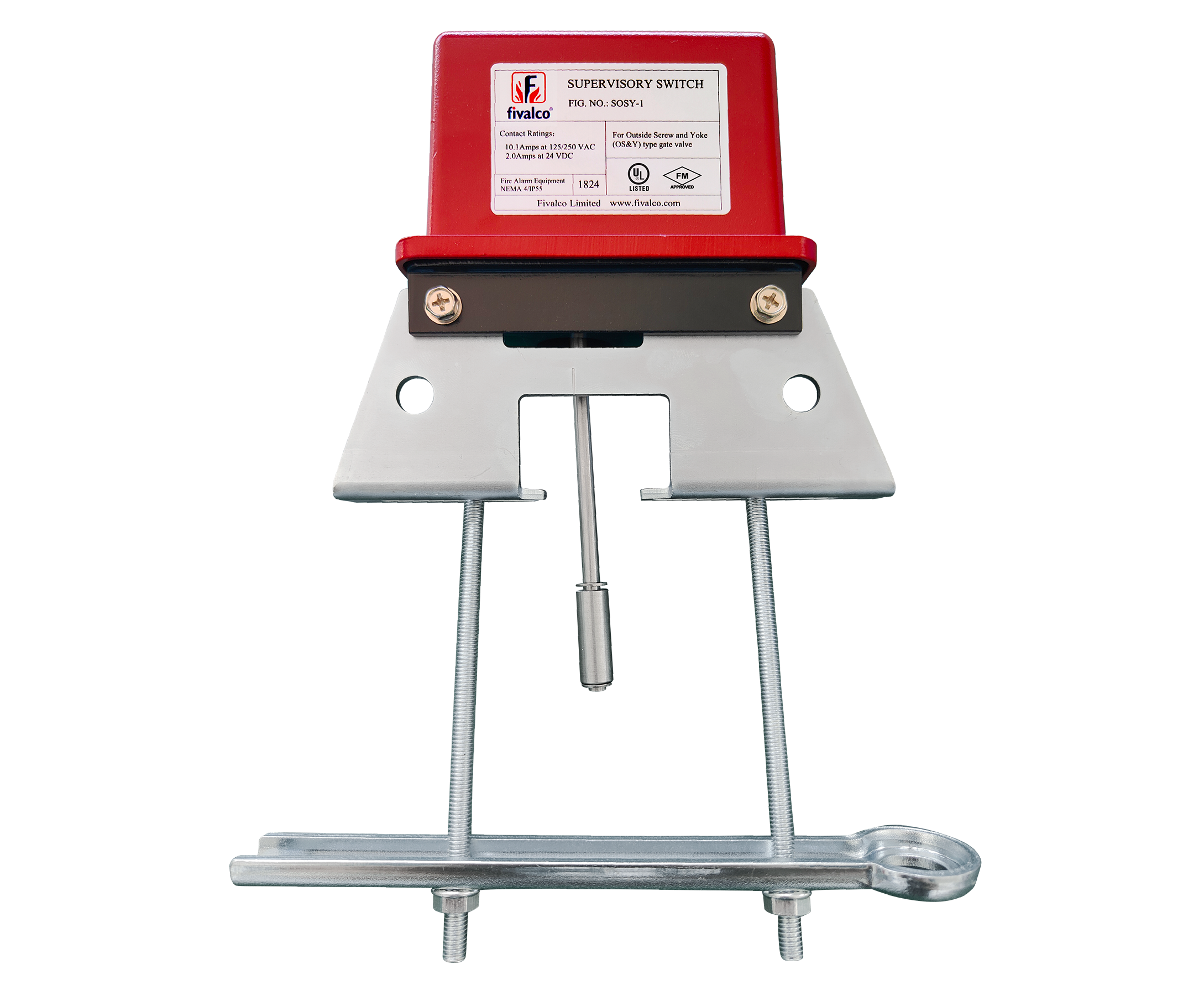
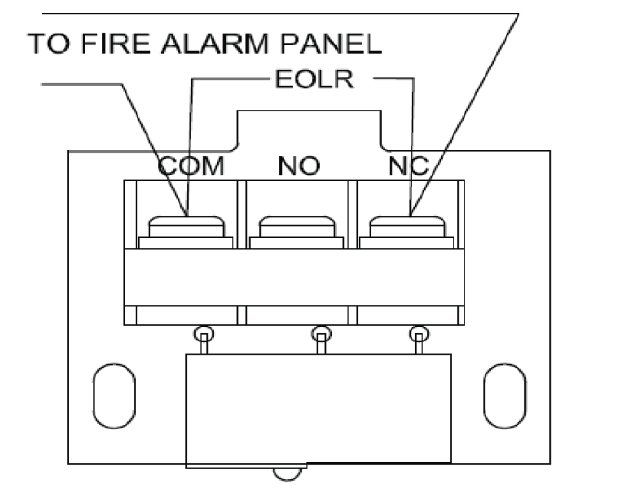
The SOSY-1 supervisory switch is installed on the Outside Screw & Yoke (OS&Y) Gate Valve and is used to monitor the open position of the valve. SOSY-1 contains one set of SPDT (Form C) contacts. These switches mount conveniently to OS&Y Gate Valves ranging from 2″ to 12″ diameter.
Operation Method
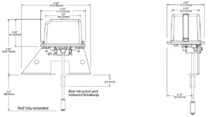
The SOSY-1 supervisory switch is a 3 position switch. The center position is the normal installation position. Normal is when the switch is installed on the OS&Y valve, the valve is fully open and the trip rod of the supervisory switch is in the groove of the valve stem. Closing the valve causes the trip rod to ride up out of the groove and activates the switches. Removing the supervisory switch from the valve causes the spring to pull the trip rod in the other direction and activates the switches.
Installation Guide
The SOSY-1 supervisory switch can be mounted on outside screw & yoke (OS&Y) gate valves between ½” and 12″ in diameter. Do not install the supervisory switch with its actuating lever pointing upward as the water may leak into the switch.
For narrow yoke valves, installing the valve with mounting bolts inside the yoke is recommended. However, some valves may have yokes that are too narrow for this positioning. If this is the case, position the bolts on the outside of the yoke.
The supervisory switch is equipped with a ground screw inside the switch housing near the conduit for applications where grounding is required.
Testing
The operation of the SOSY-1 supervisory switch and its associated protective monitoring system shall be tested, and maintained in accordance with all applicable local and national codes and standards and / or department of local authority. A minimum test shall consist of turning the valve wheel towards the closed position. The supervisory switch shall operate within the first two revolutions of the wheel. Fully close the valve and ensure that the supervisory switch does not restore. Fully open the valve and ensure that the supervisory switch restores to normal only when the
valve is fully opened.
Fully close the gate valve to ensure that the stem threads do not activate the switch. The switch being activated by the stem threads could result
in a false valve open indication.