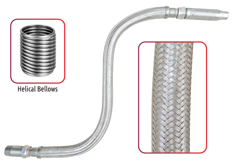
QF-1000 FLEXIBLE SPRINKLER CONNECTOR

  • QF-1000 : Braided hose
  • QF-1000E : Braided hose with elbow nipple
  • Anchoring components are intended for use with drop ceilings conforming to ASTM C635 and other major roof ceiling grid systems.
  • Standard practice for installation on metal ceiling suspension.
  • Applicable for acoustical tiles and lay-in panels, ASTM C636 or other equivalent standards.
  • Designed for use in wet and dry systems.

FM Approved, UL & ULC Listed.

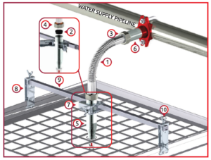
Material Specification

DET QTY Name Material
1 1 Corrugated Tube AISI 304 Stainless Steel
2 2 Sealing O-Ring EPDM
3 2 Isolation Ring Nylon 66
4 2 Slip Nut Carbon Steel ASTM 1020#, Zinc-plated
5 1 Discharge Nipples Carbon Steel ASTM 1020#, Zinc-plated
6 1 Inlet Nipples Carbon Steel ASTM 1020#, Zinc-plated
7 1 Center Brackets Carbon Steel ASTM A283M, Zinc-plated
8 2 Side Brackets Carbon Steel ASTM A283M, Zinc-plated
9 1 Square Bar Carbon Steel ASTM A283M, Zinc-plated
10 1 Set Hexagon Screws
(Options for wing screws)
Carbon Steel ASTM A283M, Zinc-plated

technical data

Working pressure: 200psi

Burst pressure: 875psi

Maximum Ambient Temperature: 150°F / 66°C

Connection: DN25 x DN15 (1″ x ½”) / DN25 x DN20 (1″ x ¾”), NPT or BSPT

Hose Diameter: O.D. 26.8mm (1-1/16″), Flow diameter 21.0mm (13/16″)

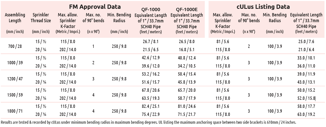
Assembling Length
(mm / inch)
In-&Outlet Head Size
(DN / in.)
Max. number of 90° bends Min bending radius
(mm / inch)
Equivalent Length of DN25/1″ Sch. 40 Pipe at C=120
QF-1000 With QF-1000E With 90° elbow
700
28
25 x 15
1″ x 1/2″
1 250
10
8.1
26.7
8
26.5
1000
40
25 x 15
1″ x 1/2″
3 250
10
12.9
42.6
12.4
40.8
1200
48
25 x 15
1″ x 1/2″
3 250
10
20.6
67.8
15.4
50.4
1500
60
25 x 15
1″ x 1/2″
4 250
10
20.6
67.8
20
65.7
1800
72
25 x 15
1″ x 1/2″
4 250
10
25.1
82.4
24.6
81

Results are tested & recorded by UL/FM approvals under minimum bending radius in maximum bending degrees.

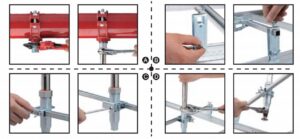
ASSEMBLY INSTRUCTIONS

A. Connect Inlet Nipple
Use pipe wrench to screw the Inlet Nipple into the branch outlet interface on water supply pipeline, use pipe sealant (Teflon tape or pipe glue etc.) to seal and apply tightening torque of approx. 50N·m/35ft-lbs. Then tighten the Hexagon Slip Nut with 15N·m/10ft-lbs to ensure sealing performance.

B. Fix bracket set
Attach side brackets to the main-rail of the T-bar grid and cross the square bar through 2 side brackets, with the center bracket in the middle. Tighten all fixing bolt on the side brackets with 4N·m/3ft-lbs.

C. Bending & Locating
Bend the Flexible Hose body as desired (According the parameters on Specification sheet) and locate the Discharge Nipple into the center bracket. Tighten the bolts on center bracket with 4N·m/3ft-lbs after the proper location of spring kier head has been found.

D. Connect Discharge Nipple
Tighten the Slip Nuts with 15N·m/10 ft-lbs and install sprinkler head to Discharge Nipple by following the sprinkler manufacture’s installation instructions. Finally test leak in according with NFPA guidelines.

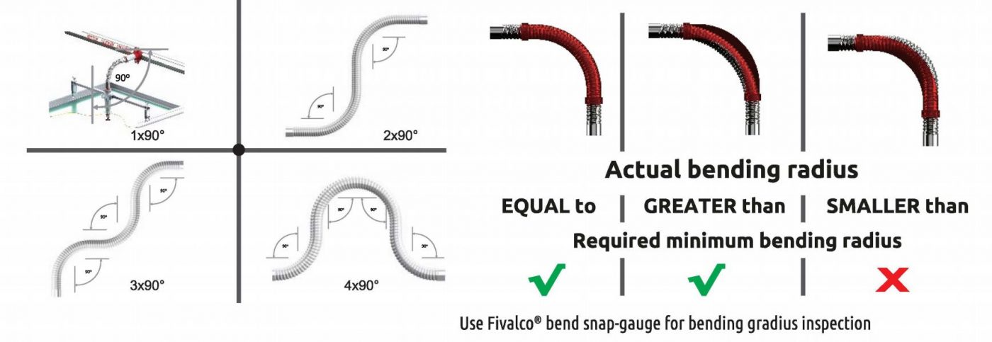
HOSE BENDING, CORRECT OR WRONG?

cALCULATION OF BENDING DEGREES

Cartoon box Pallet
Size Qty Gross weight Size Quantity Gross weight
Hose Length L W H QF-600 QF-1000 L W H Box Hose QF-600 QF-1000
mm mm mm mm ea kg kg mm mm mm ea ea kg kg
700 1050 205 195 20 27.2 31.5 1050 1050 1125 25 500 700 805
1000 1300 205 195 20 28.9 35.3 1300 1050 1125 25 500 745 905
1200 1500 205 195 20 30.2 37.7 1500 1050 1125 25 500 780 970
1500 1800 205 195 20 32 42 1800 1050 1125 25 500 830 1080
1800 2100 205 195 20 34 45.6 2100 1050 1125 25 500 885 1175

Related products

Submit An Inquiry

As a direct manufacturer, we have dedicated measurement, installation, and production teams to ensure a perfect fit every time.

Our representatives will contact you shortly to confirm your appointment date and time. Thank you for your interest!