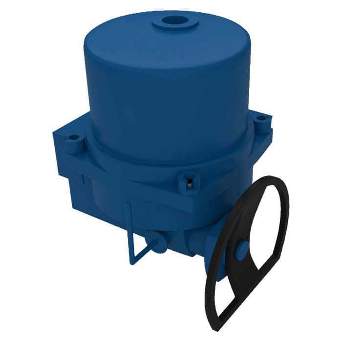
NEUMAX QT SERIES QUARTER-TURN TRANSMISSION

Fig No.: QT Series

APPLICATIONS

NEUMAX “QT” series electric actuators are designed & engineered for robust, reliable and for high performance duty onto quarter turn valves.

The unique reliable motor module, adjustable cam plate limit switch, self locking mechanism, precision gearing system and ball bearings, the auto declutching mechanism, light force load on the handwheel, the adaptor drive bushing and bottom ISO 5211 mounting dimension, are added advantages against other make in the field of valve automation. CE approved.

It is suitable for used in heating, ventilation & air-conditioning, water treatment & water-works, power generation, petrochemical plants, oil storage facilities, chemical plants, effluent treatment works, pulp & paper mills, ship building industry, etc.

Specifications

Housing & Cover Aluminium, Anodized
Enclosure Watertight IP67, Nema 4 and 6
Ambient Temperature -30°C … 70°C
Power Supply (60Hz/50Hz) 110 / 220VAC, 1 Phase
380 / 415VAC, 3 Phase
Control Power 110 / 220VAC, 1 Phase, 60/50Hz
Torque Switches 2XSPDT for QT15 and above
Limit Switches 2XSPDT 15A
Stall Protection Build-in Thermal Protection
Travel Angle 90° ± 5°
Indicator Continuous Position Indicator
Manual Override HAND / AUTO Declutching Mechanism
Self Locking Provide by means of Worm Gearing
End Stopper External Adjustable Screws
Space Heater 20W for Anti-Condensation
Conduit Entries Two G3/4″
Lubrication MoS2 Lithium Base Grease
Materials Steel, Alumimium Alloy, Aluminium Bronze
External Coating Dry Power, Epoxy-Polyester, Munsell No. FJ-002

Note : Other power supply available upon request.
Features

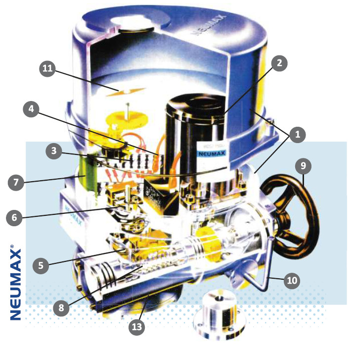
MS QT Features Diagram
1. ENCLOSURE Standard enclosure to water jet proof and water tight proof IP67, NEMA 4 & 6.
2. MOTOR Squirrel cage motor is of encapsulated type, on high stall torque and low inherent force for seating and unseating of valves. All motors are integrated with build-in thermal protection.
3. TERMINAL CONNECTION & WIRING Terminal connections are of “WAGO” push on type, making wiring connection very easy and without fuss. Electrical wiring circuit is standardized for single and three phare voltage. Addition termination is available on request.
4. INTERNAL COMPONENTS ARRANGMENT Internal mechanical and electrical components are design in modular mounting arrangement, and can be easily remove for maintenance purposes. Additional optional accessories are also possible.
5. LIMIT SWITCHES A pair limit switches are activated by means of simple, reliable and adjustable cam plates, mounted directly onto, and driven by center column. The unique cam plate design prevent over travel of limit switches.
6. TORQUE SWITCHES Electric actuators of 100 N*m and above, are install with torque switches for over-load protection.
7. HEATER For prevention of condensation due to weather and temperature changes, and also keeps internal components clean and dry, a 20 watt space heater is provided inside all the electric actuators.
8. SELF LOCKING MECHANISM Self locking mechanism with improved worm gear design.
9. HANDWHEEL Correct size of handwheel on the electric actuator ensure adequate strength for safe and efficient emergency operation.
10. MANUAL OVER-RIDE Engage by pulling and piling the lever and turning the handwheel. Lever is auto declutch when power supply is switch on, and handwheel does not turn as extra safety feature.
11. VISUAL POSITION INDICATOR The visual position indicator is directly mounted onto the center drive column to provide the visual position of the valve.
12. END STOPPERS 1 each for open and close position (adjustable), are for over travel protection.
13. MOUNTING & ADAPTATION Bottom flange mounting dimension conform to ISO 5211. An adaptor drive bushing is provided for every electric actuator. It is removable and for machining to suite valve stem size.

Performance

Type QT04 QT06 QT09 QT15 QT19 QT28 QT38 QT50 QT60 QT80 QT100 QT200 QT250
Flange ISO5211 F05/F07 F07 F07 F07/F10 F07/F10 F10/F12 F10/F12 F10/F12 F10/F12/F14 F10/F12/F14 F10/F12/F14 F16/F14 F16/F14
Max Output Torque (N*m) 40 60 90 150 190 280 380 500 600 800 1000 2000 2500
Operating Time 60/50Hz (90 Deg.) 14/17 14/17 14/17 17/20 17/20 22/26 22/26 22/26 24/29 24/29 24/29 75/90 75/90
Max Stem Dia.(mm) 14 22 22 22 22 32 32 32 42 42 42 50 50
Motor 30 min Class F(W) 10 15 25 40 40 40 60 90 120 180 200 200 200
Rated Current (mA)
1 Phase – 110V
650 1250 1500 2000 2000 2000 2700 3300 5000 5800 8000 8000 8000
Rated Current (mA)
1 Phase – 220V
300 400 550 900 900 900 1250 1600 2400 2800 3000 3000 3000
Rated Current (mA)
3 Phase – 380V
N/A N/A 190 280 280 280 400 600 800 1200 1300 1300 1300
Rated Current (mA)
3 Phase – 415V
N/A N/A 400 400 420 450 450 450 500 850 900 900 900
Number of Handle Turn 8.5 8.5 8.5 10 10 12.75 12.75 12.75 14.5 14.5 14.5 45 45
Weight (Kg) 6 9 10 12 13 17 18 19 22 23 25 35 35

Note : Without torque switches.

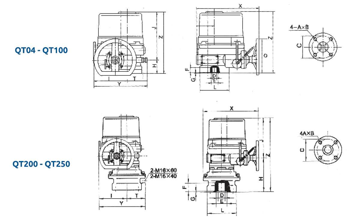
DIMENSIONS (inch/mm)

Type C A B D (Max) E F G H I J L O T X Y Z
QT04 50 M6 10 14 40 25 5 60 133 196 102 200 75 241 208 256
QT06 70 M8 14 22 55 35 5 60 133 196 102 200 75 241 208 256
QT09 70 M8 14 22 55 35 5 60 133 196 102 200 75 241 208 256
QT15 102 M10 14 22 57 35 5 64 154 199 125 250 85 272 239 263
QT19 102 M10 14 22 57 35 5 64 154 199 125 250 85 272 239 263
QT28 102 M10 17 32 75 42 5 70 174 228 145 350 100 290 274 298
QT38 102 M10 17 32 75 42 5 70 174 228 145 350 100 290 274 298
QT50 102 M10 17 32 75 42 5 70 174 228 145 350 100 290 274 298
QT60 125 M12 19 42 85 50 5 78 191 264 175 350 115 331 306 342
QT80 125 M12 19 42 85 50 5 78 191 264 175 350 115 331 306 342
QT100 125 M12 19 42 85 50 5 78 191 264 175 350 115 331 306 342
QT200 160 M20 30 50 95 60 4 241 191 264 210 350 132 357 323 505
QT250 160 M20 30 50 95 60 4 241 191 264 210 350 132 357 323 505

Related products

Submit An Inquiry

As a direct manufacturer, we have dedicated measurement, installation, and production teams to ensure a perfect fit every time.

Our representatives will contact you shortly to confirm your appointment date and time. Thank you for your interest!