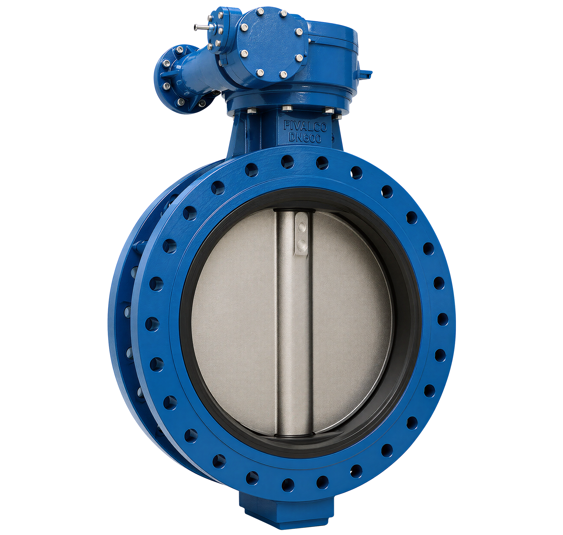
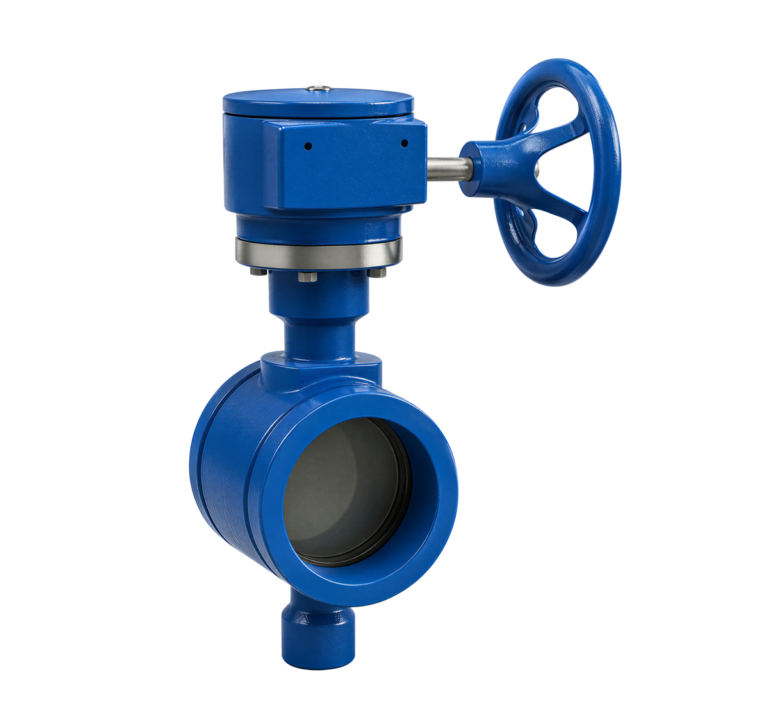
F11U U-TYPE BUTTERFLY VALVE

Fig No.: F11U16 (PN16)

FEATURES & SPECIFICATIONS

  • U-type double flange.
  • Comply with BS EN593 / BS 5155 / ISO 5752 / MSS SP-67 / API 609.
  • Flange drilled to BS 4504 PN16 / EN1092-2 PN16 / ANSI Class 150 / JIS10K / AS 2129 Table E (Specify on order).

PRESSURE & TEMPERATURE RATINGS

Working Pressure 16bar
Shell Testing Pressure (x1.5) 24bar
Seat Testing Pressure (x1.1) 17.6bar
Working Temperature -20°C … 110°C (EPDM)
-10°C … 80°C (NBR)
Suitable Media Water, Oil, Gas

Material Specification

Part Material
Body Ductile Iron
Disc Ductile Iron
Aluminium Bronze
Stainless Steel 304
Stainless Steel 316
Stem Stainless Steel 410
Stainless Steel 431
Seat Ring EPDM / NBR
O-Ring EPDM / NBR
Bushing Bronze

DIMENSIONS

DN (mm)
(inch)
150
6
200
8
225
9
250
10
300
12
350
14
375
15
400
16
450
18
500
20
550
22
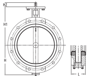
A 133 175 190 201 242 267 320 316 344 380 432
B 226 260 275 292 337 368 375 400 422 480 533
C 30 34 34 34 34 40 52 52 52 64 70
L 55 60 67 67 76 76 102 102 114 127 151
DN (mm)
(inch)
600
24
650
26
700
28
750
30
800
32
900
36
1000
40
1050
42
1100
44
1200
48
A 468 484 530 564 602 661 724 784 804 869
B 562 540 626 660 666 722 806 865 820 938
C 70 70 95 95 95 130 130 150 150 150
L 151 172 165 167 188 203 216 251 252.5 276
Cast Iron 1 – Stage Worm Gear and Handwheel
Carbon Steel Gear Box Shaft
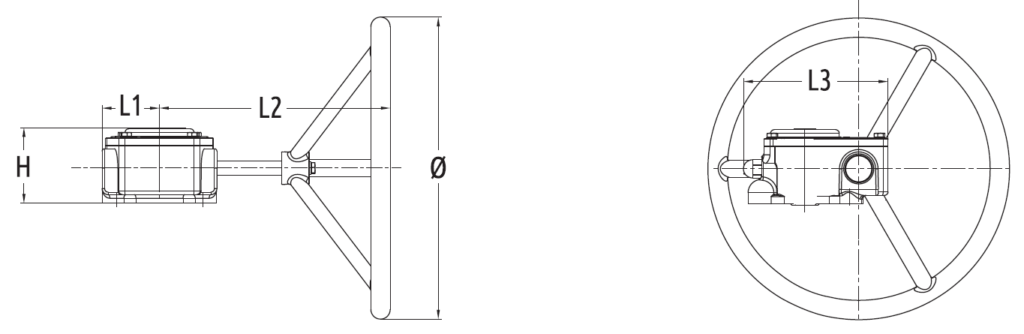
Valve Diameter D1 ø H H1 L1 L2 L3
DN150 90 150 33 70 216 45 127
DN200…DN250 125 285 36 76 303 63.5 170
DN300…DN350 125 285 40 79 300 80 190
DN375…DN400 175 385 79 323.5 300 80 190
DN450…DN550 175 390 108 251 397/427 120 279
Cast Iron 2 – Stage Worm Gear and Handwheel
Carbon Steel Gear Box Shaft
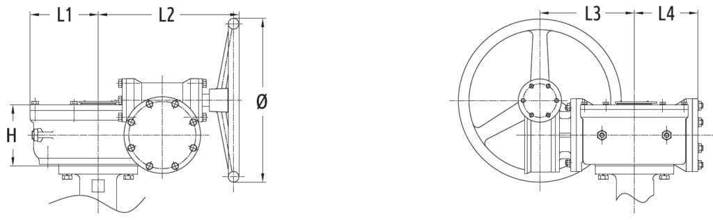
Valve Diameter D1 ø H H1 L1 L2 L3 L4 L5
DN600…DN650 210 285 125 271 107 100 156 168 107
DN700…DN800 300 425 149 378 146 140 197 230 146
DN900…DN1050 300 425 185 409 201 196 203 279 201
DN1100 350 425 185 409 201 196 203 279 201
DN1200 350 425 216 423 185 240 203 311 255

INSTALLATION & OPERATION GUIDE

1. Ensure sufficient space for valves for easy installation, operation, maintenance and replacement.
2. Verify the valves are suitable for the operating condition such as medium, operating pressure / temperature, etc.
3. Check the I.D. of the flange and pipe to ensure free disc movement.
4. Valves shall be mounted on flanges only after the counter flanges have been welded to pipe and cooled down to the atmospheric temperature. Welding heat may damage the rubber seat of the valves. Never weld the flanges with valves installed. No gasket is required for installation of rubber seated butterfly valves.
5. Position the valves carefully between flanges. Accurate centering between flanges is essential to prevent any damages and problems during operation.
6. Valves should be installed by placing bolts through the hole and tightening carefully, ensuring even contact between the flange and seat. Too tight of space may cause damages to the seat and should be avoided.
7. Cross tighten all the bolts diagonally to distribute the loads evenly over the valves.
8. Turning the valves to ensure sufficient disc clearance.
9. Valves equipped with manual operators must be operated manually. Excessive external force on the operation of valve may damage the valve and / or operator.
10. Blind flange with short pipe should be used for dead end installation.

Related products

Submit An Inquiry

As a direct manufacturer, we have dedicated measurement, installation, and production teams to ensure a perfect fit every time.

Our representatives will contact you shortly to confirm your appointment date and time. Thank you for your interest!