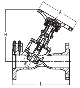
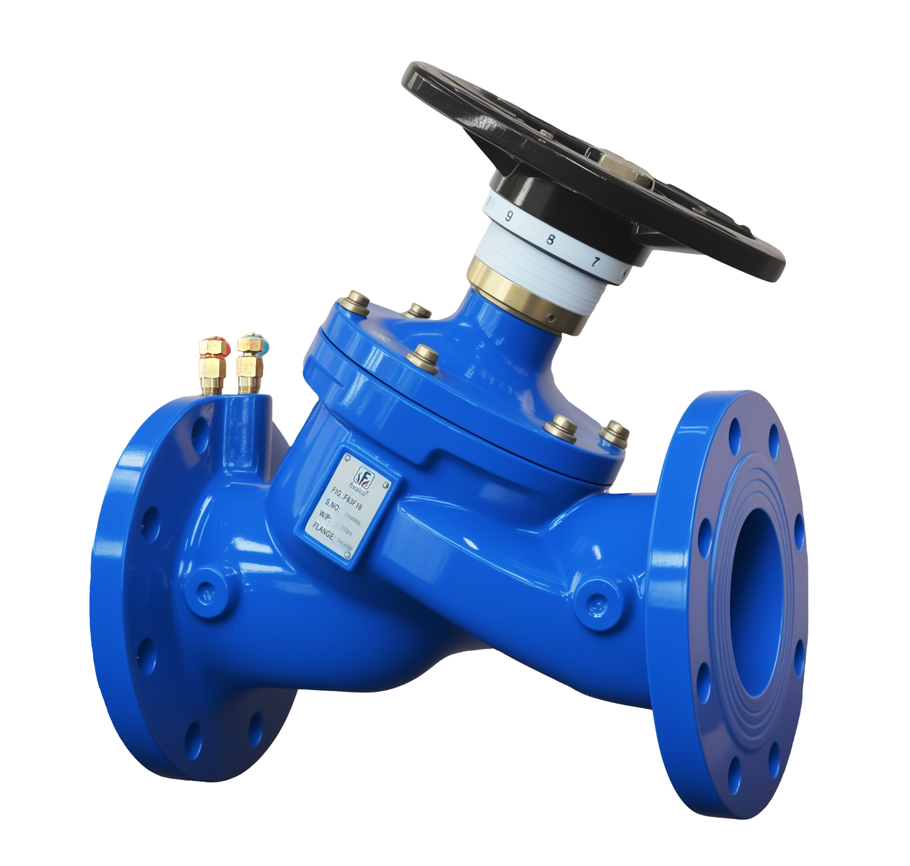
F63F FIXED ORIFICE DOUBLE REGULATING VALVE

Fig No.: F63F16 (PN16) / F63F25 (PN25)

FEATURES & SPECIFICATIONS

  • Single unit Y-pattern globe valves incorporating fixed orifice plate flow measurement unit.
  • Fitted with a pair of measuring plugs.
  • High measurement accuracy of +/-5% across all opening settings.
  • Microset handwheel and presetting scale is readable from all directions.
  • Regulating and isolating functions.
  • Setting can be locked with allen key.
  • Flange drilled to BS 4504 PN16 / EN 1092-2 PN16 / BS 4504 PN25 / EN 1092-2 PN25 / ANSI Class 150 (Specify on order).
  • Comply with BS 7350.
  • Applicable for hydronic balancing of heating and cooling systems.

PRESSURE & TEMPERATURE RATINGS

Working Pressure 16bar / 25bar
Shell Testing Pressure (x1.5) 24bar / 37.5bar
Seat Testing Pressure (x1.1) 17.6bar / 27.5bar
Working Temperature -10°C … 120°C
Suitable Media Water

Material Specification

Part Material Specification
Body Ductile Iron EN-JS 1050
Bonnet Ductile Iron EN-JS 1050
Stem Stainless Steel 410(DN65…DN300)
Stainless Steel 431(DN350…DN600)
EN 10088-3 1.4006
EN 10088-3 1.4057
Balancing Cone Ductile Iron EN-JS 1050
Disc EPDM coated DI EN-JS 1050
Gland Brass (DN65…DN150)
Ductile Iron (DN200…DN600)
EN 12165 CW617N
EN-JS 1050
Gland Nut Brass EN 12165 CW617N
Orifice Insert DZR Brass EN 12165 CW602N
Measuring Plug DZR Brass EN 12165 CW602N
Handwheel Ductile Iron EN-JS 1050
Packing Graphite Non-Asbestos

DIMENSIONS

DN (mm)
(inch)
65
21/2
80
3
100
4
125
5
150
6
200
8
250
10
300
12
350
14
400
16
450
18
500
20
600
24
L 290 310 350 400 480 600 730 850 980 1100 1200 1250 1450
H 265 270 310 340 340 537 570 690 685 965 1020 1065 1180
D 200 200 240 290 290 350 420 420 420 640 640 640 640
Kvs(Fully Open) 104 116 213 333 476 768 1153 1743 1798 2338 2698 3708 4500
Handwheel Turns 8 8 8 8 8 12 12 18 18 24 24 24 24
DN (mm)
(inch)
65
21/2
80
3
100
4
125
5
150
6
200
8
250
10
300
12
Kvs 104.00 116.00 213.00 333.00 476.00 768.00 1153.00 1743.00
DN (mm)
(inch)
350
14
400
16
450
18
500
20
600
24
Kvs 1798.00 2338.00 2698.00 3708.00 4500.00

INSTALLATION & OPERATION GUIDE

Install the Double Regulating Valve in the pipe line by ensuring the arrow marking on the valve is same direction as piping flow.

To achieve flow measurement accuracy, it is essential that the piping on the inlet and outlet of the valve is straight and has a minimum length equivalent to 5 Diameters (5D) inlet and 2 Diameters (2D) outlet as shown. If the valve is install at the discharge side of a pump set, it is essential that the straight pipe length between pump outlet and valve has a minimum length of 10 Diameters (10D).

Gaskets must be used and assembled between valve and flanges. This will ensure the installation is concentric with pipe line and better accuracy is obtained.

Design flow is achieved by pre-setting valve’s opening position, which could be read from scales at the handwheel. Contact your local distributor for information on electronic commissioning meter.

To lock the pre-setting of the valve, push the limitation ring at the scales at the bottom of the handwheel, tighten the screw using the hexagon wrench.

Valve must not be lifted by holding the handwheel.

Related products

Submit An Inquiry

As a direct manufacturer, we have dedicated measurement, installation, and production teams to ensure a perfect fit every time.

Our representatives will contact you shortly to confirm your appointment date and time. Thank you for your interest!