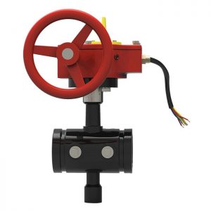
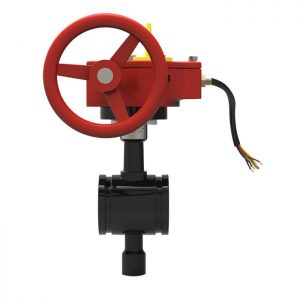
Material Specification
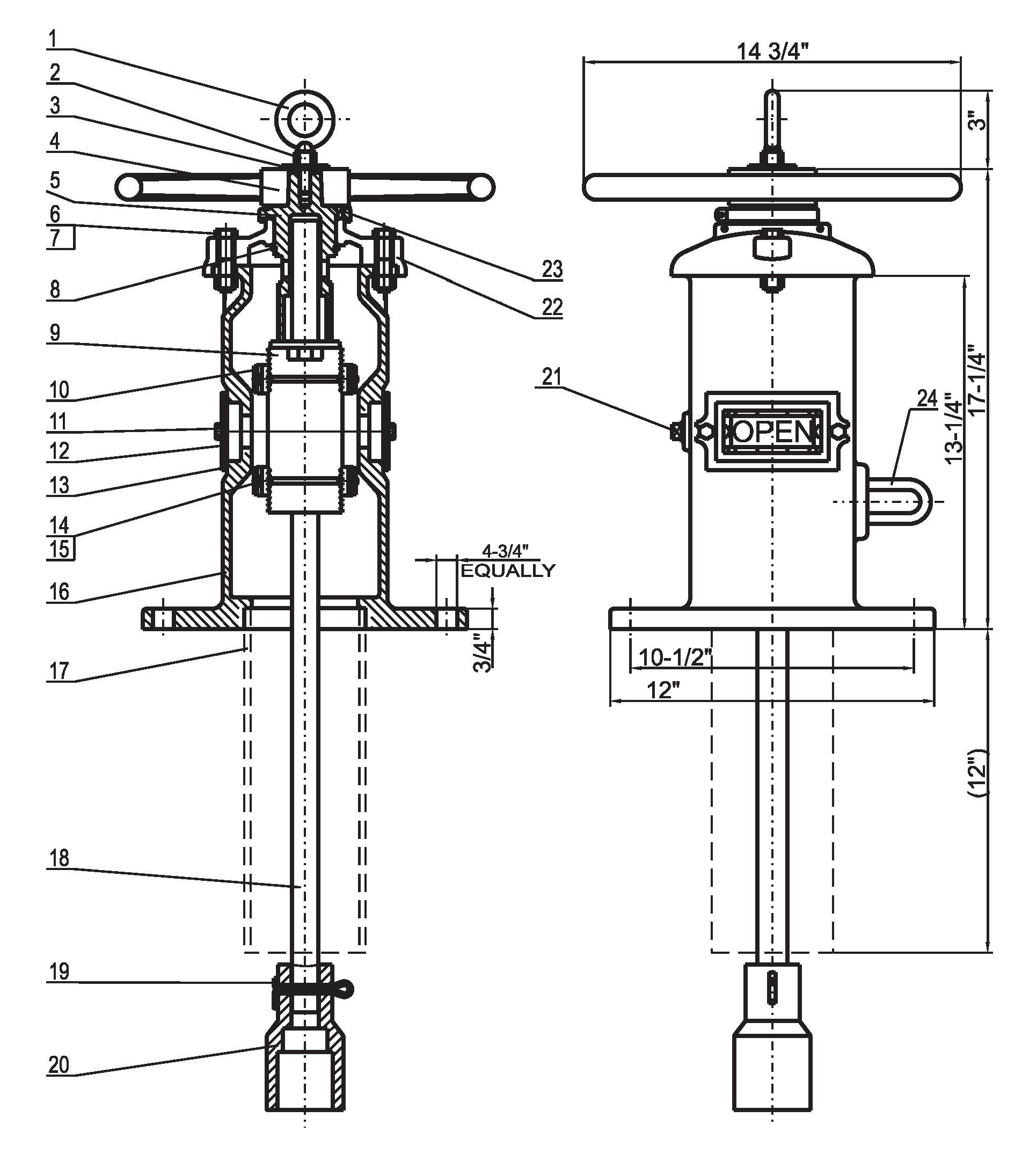
| No. | Qty. | Name | Material |
|---|---|---|---|
| 1 | 1 | Lifting Eye Bolt | ASTM A105 |
| 2 | 1 | Hex Nut | ASTM A105 |
| 3 | 1 | Washer | ASTM A105 |
| 4 | 1 | Hand Wheel | ASTM A105 |
| 5 | 1 | Operating Nut | ASTM A105 |
| 6 | 2 | Hex Cap Screw | ASTM A105 |
| 7 | 2 | Hex Nut | ASTM A105 |
| 8 | 1 | Snap Ring | AISI 066 |
| 9 | 1 | Target Carrier Nut | ASTM B62 |
| 10 | 4 | Target | ASTM B108 |
| 11 | 4 | Hex Cap Nut | ASTM A105 |
| 12 | 2 | Window Glass | LEXAN-UM |
| 13 | 2 | Window Glass Gasket | PTFE |
| 14 | 4 | Hex Cap Screw | ASTM A105 |
| 15 | 4 | Hex Nut | ASTM A105 |
| 16 | 1 | Body | ASTM A536 |
| 17 | 1 | Stand Pipe | ASTM A53 |
| 18 | 1 | Stem | AISI 1045 |
| 19 | 1 | Cotter Pin | AISI 304 |
| 20 | 1 | Crane Coupling | ASTM A536 |
| 21 | 1 | Plug | AISI 304 |
| 22 | 1 | Cover | ASTM A126B |
| 23 | 1 | Cross Recessed Counter Sunk Head Screw |
AISI 304 |
| 24 | 1 | Locking Nose | ASTM 307B |
FIELD ADJUSTMENT
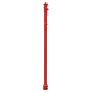
1. Remove the top section from the top of the Indicator Post assembly.
2. Set the “OPEN” and” SHUT” targets for the appropriate valve size.
3. Reattach the Top Section to the top of the Indicator Post assembly.
4. Design and dimensions are subject to change without notice.
