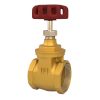
ระดับความดันและอุณหภูมิ
| ความกดดันจากการทำงาน | 16bar |
| Shell Testing Pressure (x1.5) | 24bar |
| Seat Testing Pressure (x1.1) | 17.6bar |
| อุณหภูมิในการทำงาน | -20°C … 110°C (EPDM) -10°C … 80°C (NBR) |
| สื่อที่เหมาะสม | น้ำ น้ำมัน และก๊าซ |
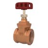
ข้อมูลจำเพาะของวัสดุ
| ตัวเครื่อง | เหล็กดัด |
| ดิสก์ | เหล็กดัด อลูมิเนียมบรอนซ์ สแตนเลส 304 สแตนเลส 316 |
| เพลา | สแตนเลส 410 สแตนเลส 431 |
| แหวนที่นั่ง | EPDM / NBR |
| โอริง | EPDM / NBR |
| บูช | สีบรอนซ์ |
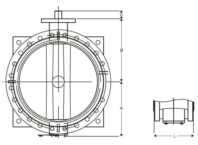
ขนาด
| DN | (มม.)
(นิ้ว) |
50
2 |
65
21/2 |
80
3 |
100
4 |
125
5 |
150
6 |
200
8 |
250
10 |
300
12 |
350
14 |
400
16 |
450
18 |
500
20 |
600 24 |
| A | 82.5 | 92.5 | 100 | 110 | 125 | 142.5 | 170 | 202.5 | 230 | 260 | 290 | 320 | 357.5 | 430 | |
| B | 127.5 | 136 | 146 | 156 | 176 | 186.5 | 226 | 274 | 304 | 330 | 340 | 400 | 500 | 535 | |
| C | 56 | 56 | 56 | 56 | 56 | 56 | 70 | 70 | 76 | 76 | 107 | 107 | 107 | 135 | |
| L | 108 | 112 | 114 | 127 | 140 | 140 | 152 | 165 | 178 | 190 | 216 | 222 | 229 | 267 |
| DN | (มม.)
(นิ้ว) |
700
28 |
800
32 |
900
36 |
1000
40 |
1200
48 |
1300
52 |
1350
54 |
1400
56 |
1500
60 |
1600
64 |
1800
72 |
2000
80 |
2200
88 |
2400 96 |
| A | 507 | 573 | 634 | 693 | 789 | 968 | 1066 | 1055 | 1025 | 1041 | 1164 | 1350 | 1430 | 1610 | |
| B | 560 | 620 | 620 | 735 | 917 | 990 | 1046 | 1000 | 1060 | 1150 | 1200 | 1360 | 1500 | 1650 | |
| C | 130 | 130 | 130 | 150 | 150 | 200 | 200 | 200 | 200 | 200 | 200 | 200 | 300 | 300 | |
| L | 292 | 318 | 318 | 410 | 470 | 490 | 490 | 530 | 570 | 600 | 670 | 760 | 800 | 850 |
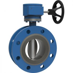
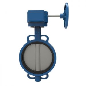
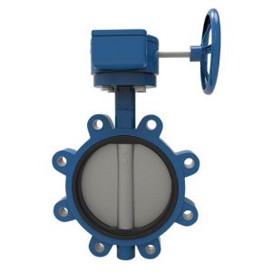
Cast Iron 1 – Stage Worm Gear and Handwheel
เพลากล่องเกียร์เหล็กกล้าคาร์บอน
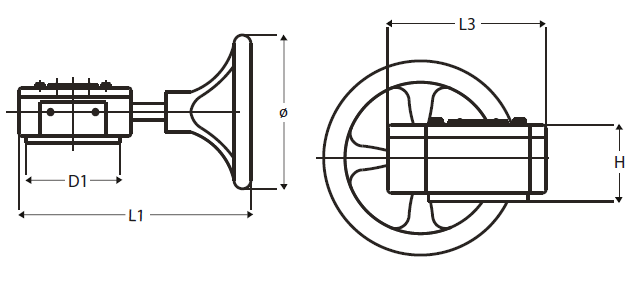
| เส้นผ่านศูนย์กลางของวาล์ว | D1 | ø | H | L1 | L3 |
| DN50 – DN80 | 65 | 150 | 33 | 216 | 127 |
| DN100 – DN150 | 90 | 150 | 33 | 216 | 127 |
| DN200 – DN250 | 125 | 285 | 36 | 303 | 170 |
| DN300 – DN350 | 125 | 285 | 40 | 300 | 190 |
| DN400 | 175 | 385 | 79 | 300 | 190 |
| DN450 – DN500 | 175 | 390 | 108 | 397/427 | 279 |
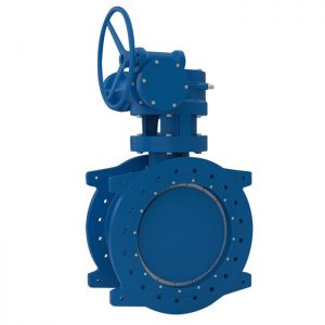
Cast Iron 2 – Stage Worm Gear and Handwheel
เพลากล่องเกียร์เหล็กกล้าคาร์บอน
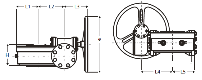
| เส้นผ่านศูนย์กลางของวาล์ว | ø | H | L1 | L2 | L3 | L4 | L5 |
| DN400 – DN500 | 285 | 125 | 107 | 100 | 156 | 168 | 107 |
| DN600 | 285 | 125 | 107 | 100 | 156 | 168 | 107 |
| DN700 – DN800 | 425 | 149 | 146 | 140 | 197 | 230 | 146 |
| DN900 – DN1000 | 425 | 185 | 201 | 196 | 203 | 279 | 201 |
| DN1200 | 425 | 216 | 185 | 240 | 203 | 311 | 255 |
| DN1300 – DN1400 | 510 | 267 | 208 | 345 | 258 | 435 | 355 |
| DN1500 – DN1600 | 510 | 312 | 316 | 410 | 237 | 450 | 425 |
| DN1800 | 510 | 326 | 360 | 460 | 237 | 466 | 475 |
| DN2000 | 600 | 480 | 410 | 602 | 265 | 725 | 630 |
| DN2200 – DN2400 | 600 | 570 | 442 | 696 | 364 | 742 | 726 |
คู่มือการติดตั้งและการใช้งาน
- ตรวจสอบให้แน่ใจว่ามีพื้นที่เพียงพอสำหรับวาล์วเพื่อให้ติดตั้ง ใช้งาน บำรุงรักษา และเปลี่ยนได้ง่าย
- ตรวจสอบว่าวาล์วเหมาะสมกับสภาพการใช้งาน เช่น ปานกลาง แรงดันใช้งาน / อุณหภูมิ ฯลฯ
- ตรวจสอบไอดี ของหน้าแปลนและท่อเพื่อให้แน่ใจว่ามีการเคลื่อนที่ของแผ่นดิสก์อย่างอิสระ
- Valves shall be mounted on flanges only after the counter flanges have been welded to pipe and cooled down to the atmospheric temperature. Welding heat may damage the rubber seat of the valves. Never weld the flanges with valves installed. No gasket is required for installation of rubber seated butterfly valves.
- Position the valves carefully between flanges. Accurate centering between flanges is essential to prevent any damages and problems during operation.
- Valves should be installed by placing bolts through the hole and tightening carefully, ensuring even contact between the flange and seat. Too tight of space may cause damages to the seat and should be avoided.
- ขันสลักเกลียวทั้งหมดให้แน่นตามแนวทแยงมุมเพื่อกระจายโหลดให้เท่ากันทั่ววาล์ว
- หมุนวาล์วเพื่อให้แน่ใจว่ามีระยะห่างของแผ่นดิสก์เพียงพอ
- Valves equipped with manual operators must be operated manually. Excessive external force on the operation of valve may damage the valve and / or operator.
- Blind flange with short pipe should be used for dead end installation.